Reactor support platforms
Preliminary structural assessment of a three-module bolted platform carrying two new agitated reactors alongside an existing one. Linear static screening, run in three stages to a final resolved configuration.
Chemical production line
Capacity expansion & upgrade
Linear static screening
Global stiffness & load path
SolidWorks
SolidWorks Simulation
EN 1993-1-1 (working)
EN 1993-1-8 (next phase)
The looser L/250 was available and passed. The stricter L/300 was kept, and the tenth-of-a-millimetre exceedance is declared rather than argued away — accepted against the severe conservatism of the load case. Section 7 makes the argument.
| Rev | Change | Governing X displacement | Status |
|---|---|---|---|
| Rev 0 | Original configuration screened as received | 57 mm · fails, no bracing in X | Superseded |
| Rev 1 | Full corrective package: bracing, diaphragms, stiffeners, resized members | 30 mm · effective, still short | Superseded |
| Rev 2 | Intermediate discharge columns beneath the reactors, strong axis on X | 17 mm · resolved, taken forward | Final |
The brief
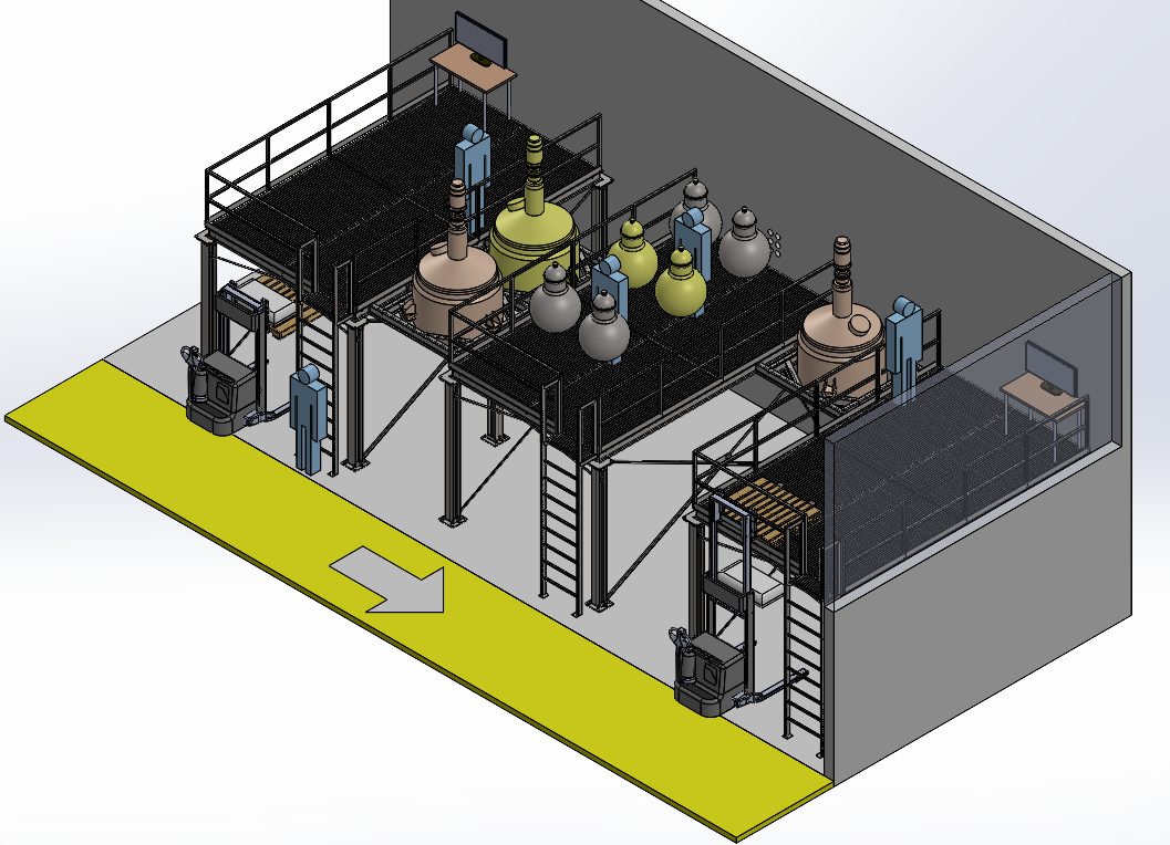
Background & premisesThe client runs a chemical production line built around a single reactor and wants to roughly triple output by adding two more. The commercial driver is capacity. The engineering driver is that the existing installation had stopped being defensible: the reactor was charged from a step ladder, it sat on a plain rectangular frame that was corroded, patched and reinforced in place with welds clearly meant to hide a problem rather than solve one, and the distillation flasks were strapped to scaffolds that had quietly become permanent supports.
So the expansion budget was also the opportunity to make the installation safe. That framing mattered for every decision that follows.
The corrosion allowance is deliberate, not conservatism
The environment is aggressive on two fronts at once. Mechanically, the agitated reactors drive the structure in every horizontal direction. Chemically, the exposure peaks during reactor cleaning — the product reacts with water and attacks steel quickly, and cleaning is precisely when the structure meets it.
I proposed a non-reactive material and the client ruled it out immediately: carbon steel would do, they would be careful during cleaning, and the structure would be scraped and repainted on a maintenance cycle.
A promise to be careful is not a design input. So I sized the members well above the strict requirement — not as a safety margin, but as sacrificial thickness. Members are selected so that after the expected wall loss over the maintenance interval, the remaining corroded section still passes the design checks. The as-new section is not what the structure is verified on.
Loading, with the motor still undefined
The agitator motor could not be obtained in time — procurement wanted to compare options, and the project department wanted to proceed anyway. The reactor's centre of gravity is therefore not known with certainty: the model is a simplified 3-D representation rather than the real components and their true masses, and the vessel is not filled to capacity because free volume is left for the charge to move during mixing.
Rather than chase an exact load point I could not justify, I applied the theoretical maximum charge amplified by a factor of 1.5 over the client's nominal working figure, and represented the mixing action as that amplified load able to act in any horizontal direction. That bounds the centrifugal effect conservatively without pretending to a precision the inputs do not support. The modal verification stays on hold until speed, rotating mass and imbalance arrive.
Two constraints the client would not trade
- Clear access beneath the platforms. The lower level stores the raw material fed to the reactors and has to be reachable by forklift. Bracing cannot close it.
- A single erection day, booked two weeks out. The production manager will not release installation days with more notice than that. So the platforms are designed as bolted assemblies, erected by three crews of two in eight hours — twelve if needed — on a Thursday or Friday. The reactor sub-frames are the exception: shop-prefabricated, welded in place, cut deliberately long so they can be trimmed to absorb misalignment. That welding happens in an ATEX-classified zone with the existing reactor lifted, which is its own planning problem.
Staged approach: linear static screening first. Eigenvalue buckling, the second-order check and code-level verification of bolted and welded connections run only once the structure passes the screening in every direction. There is no value in characterising later limit states on a configuration already known to fail an earlier one.
Revision 0 — screening what was proposed
Rev 0 · figures 1–15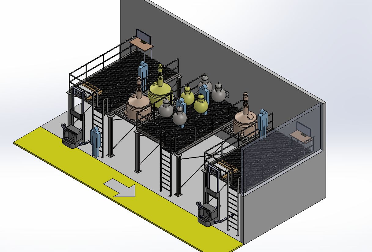
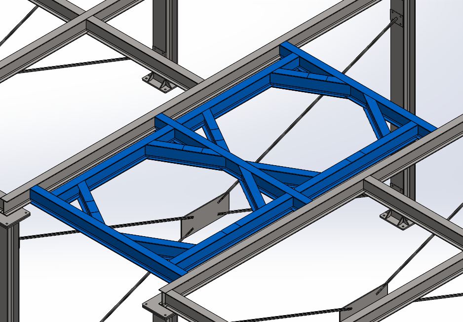
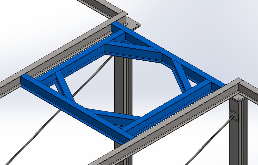
Load case G+Z — mostly acceptable, two things worth reading
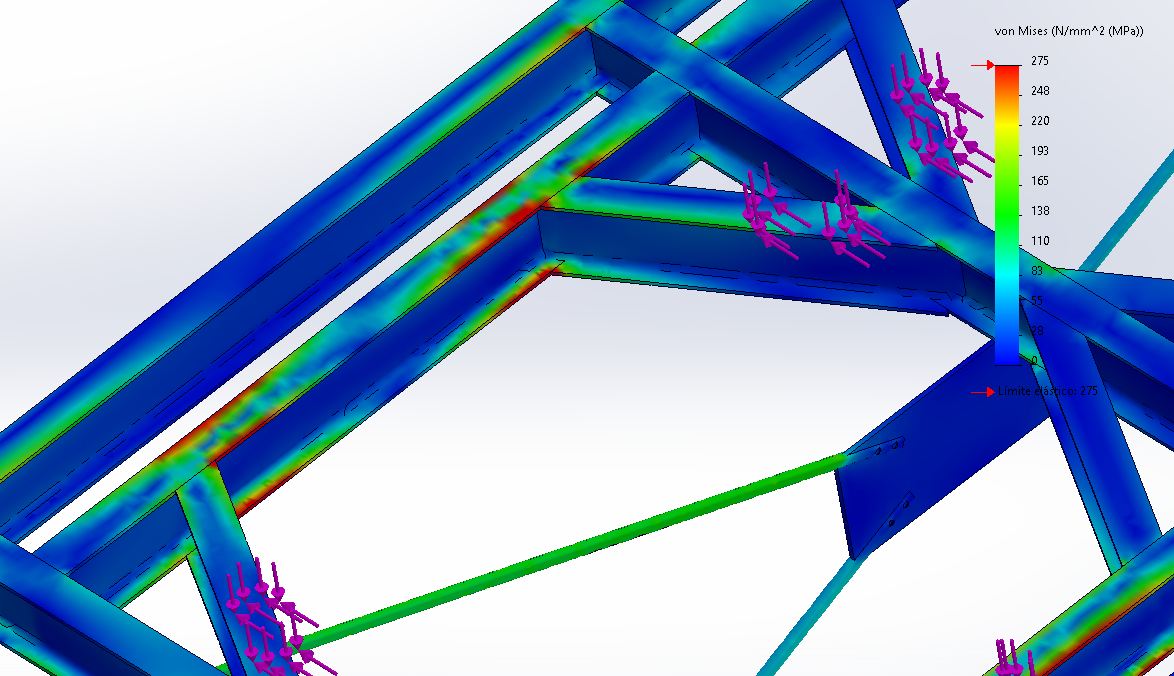
Reactor 3's frame is satisfactory: von Mises stress stays comfortably below yield. The frame carrying reactors 1 and 2 does not, and shows several zones that have to be resolved before the design can be called adequate.
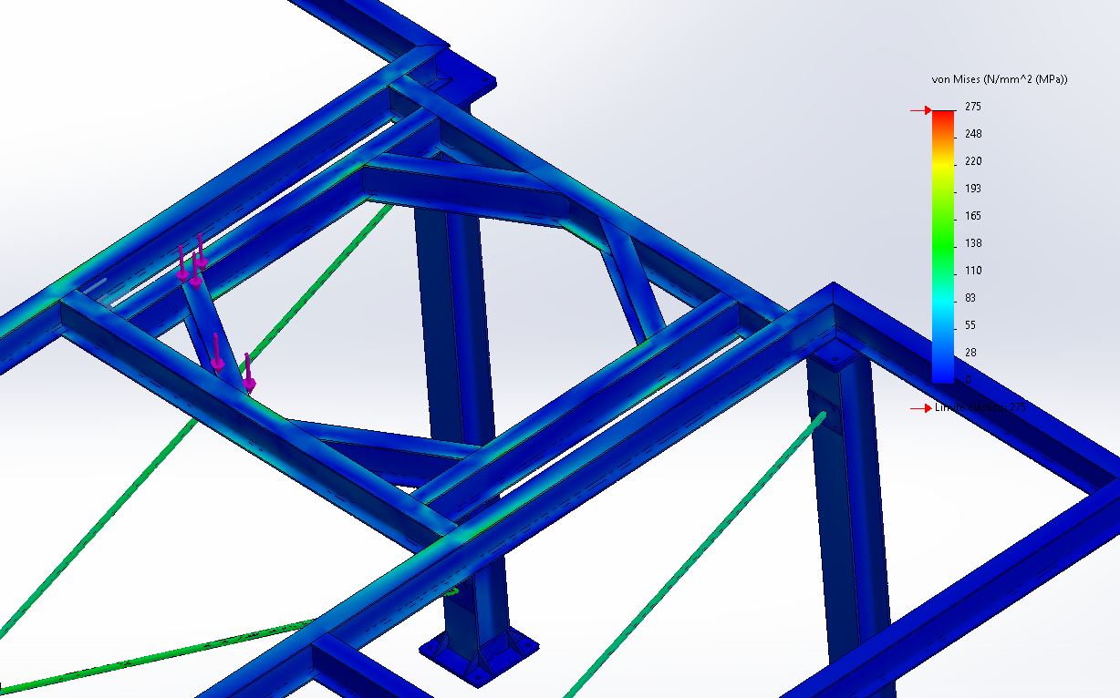
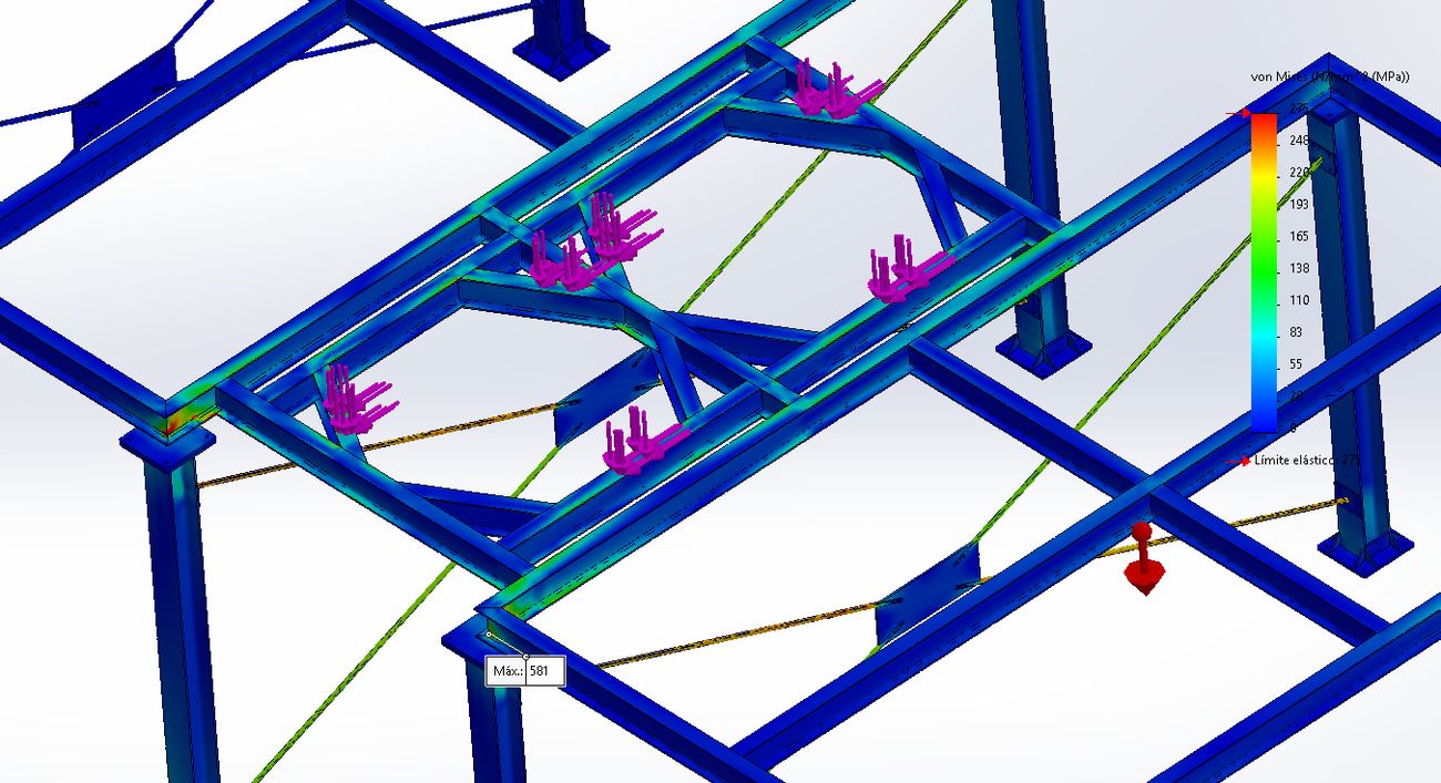
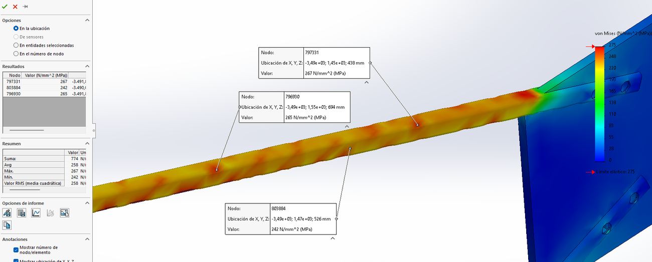
The braces sit very close to yield with the 20 × 20 hollow section. The client wanted to use stock left over from another job on the argument that it would be "sufficient"; the analysis says otherwise. As an economical alternative I proposed reusing the section already adopted for the guardrails.
What matters is how the replacement gets chosen. Under a reversing mixing load the braces carry compression, not just tension, so the governing check is buckling slenderness and section classification to EN 1993-1-1 — not simply picking something larger. A 40 × 40 × 2 hollow section or an angle are both candidates; the compression check decides.
Reading a red patch that is not a failure
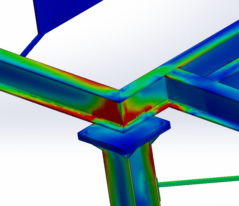
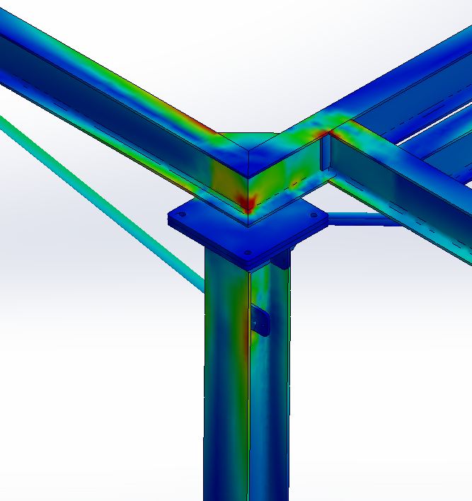
The mitred welded joints are modelled with sharp, non-radiused geometry. They light up red, and those readings are disregarded. At a sharp reentrant corner the computed peak does not converge — it keeps climbing as the mesh is refined — so it is an artefact of the modelled geometry, not a yield criterion. The value used to assess the member is the nominal stress read roughly one wall thickness away from the weld toe.
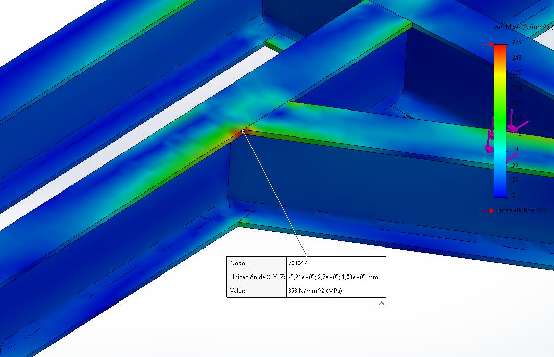
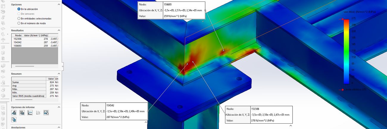
The corners themselves still need a constructive fix. My proposal is to use the same I-section, cut as a double mitre and welded on the inner face, to enlarge the node and spread the load. There is a fatigue argument underneath: under the cyclic mixing action the weld toe at that reentrant corner is the most likely crack-initiation site, so the enlarged node has to be finished with a radius or a ground weld toe. Otherwise it moves the peak a few millimetres instead of removing it.
Load case G+X — the structure fails
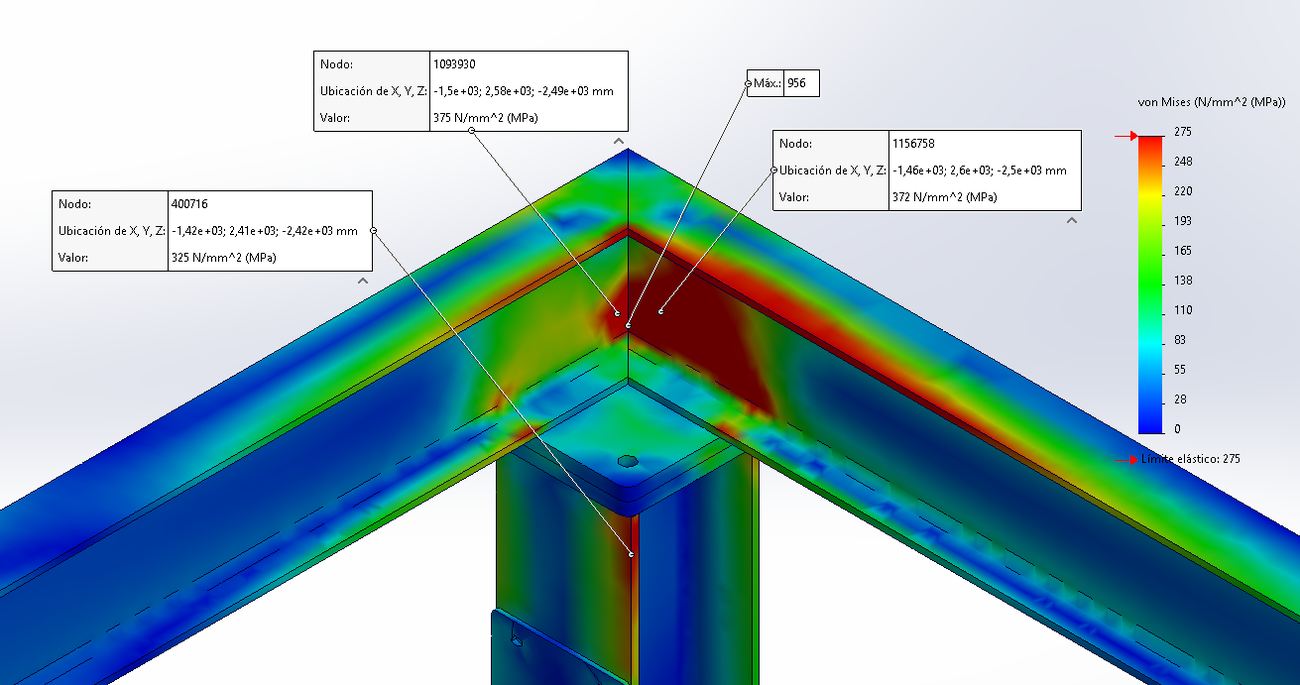
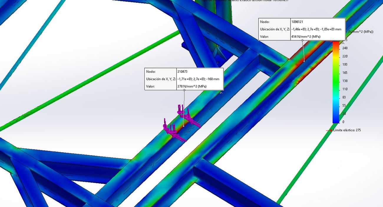
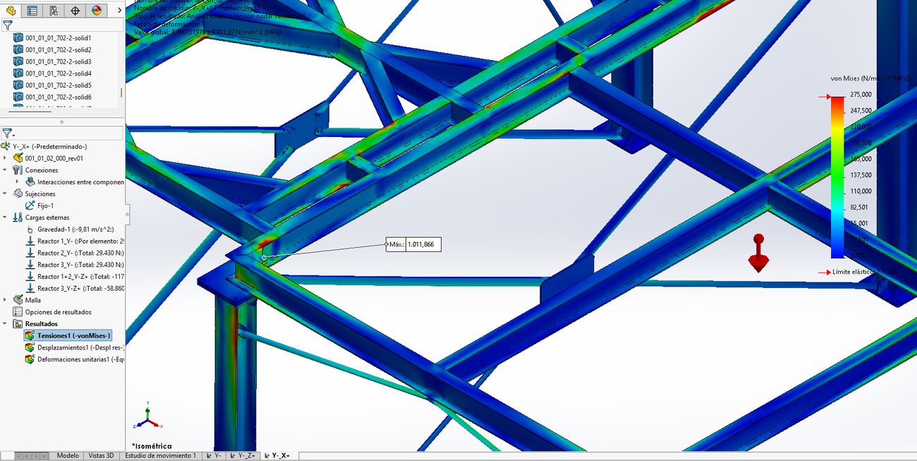
The 956 MPa recorded at the reentrant corner is the same singularity as before and is disregarded. The stresses adjacent to it are not: they sit well above the theoretical yield of the selected material and call for resizing or a constructive measure to redistribute the load. The reactors also impose torsion on the I-sections, which will likely need haunching or gusseting to control.
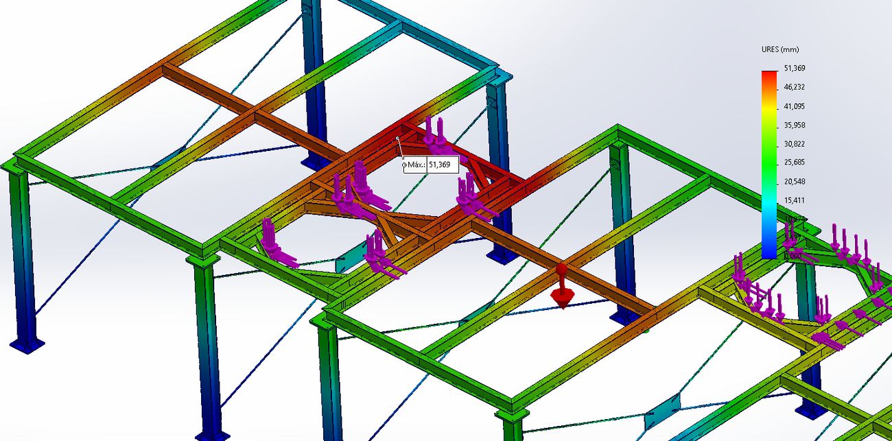
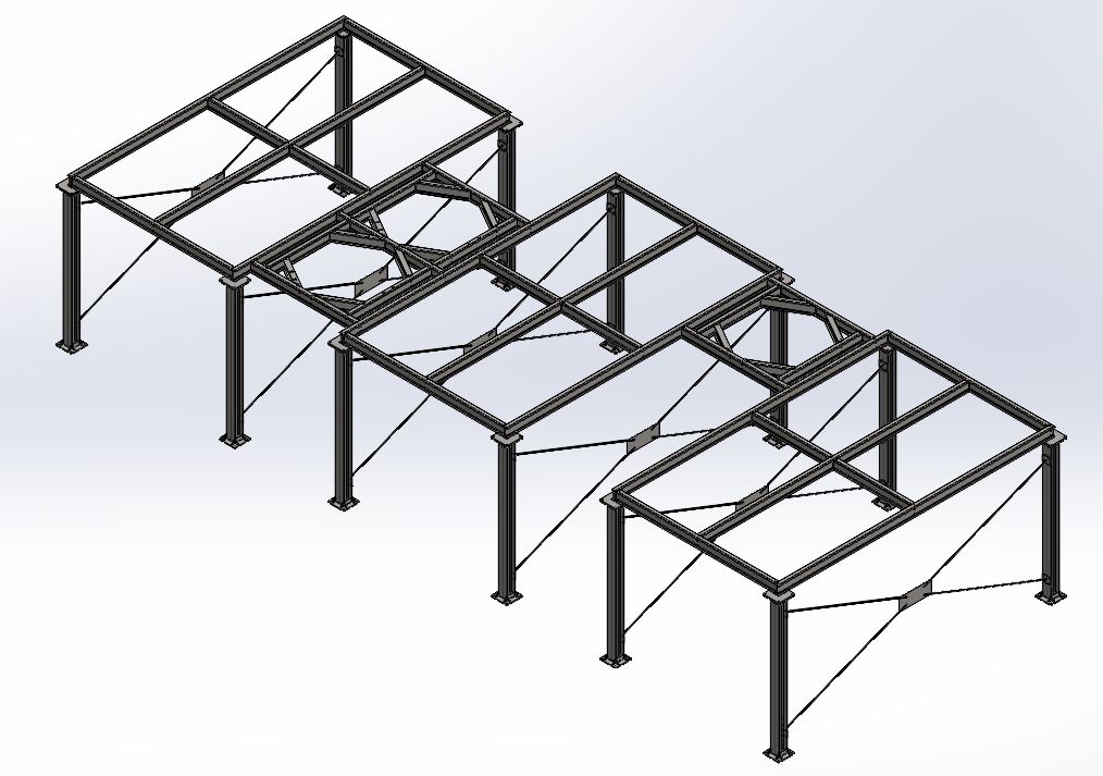
There is no bracing whatsoever in this axis, and the structure is fully exposed to lateral action — visible even in a linear analysis. The displacement plot confirms it: global sway, 57 mm at worst.
The bracing strategy then has to be reconciled with the two constraints the client would not trade. The proposal: St. Andrew's cross bracing used generously, ties between the three platforms so the modules act together rather than independently, and horizontal diaphragm bracing in the upper plane of each module. The diaphragm carries lateral load to the braced rear plane and leaves the front face and the underside open for forklift access and material storage. Tying the platforms together means their interconnections now transmit lateral load, so those connections become items to verify at the connection stage — and the whole scheme has to fit the bolted single-day erection window.
What Rev 0 concluded
Two governing deficiencies: a complete absence of bracing in X, and braces underdesigned for the demand. Supporting evidence that points the same way — in the columns the flanges are overworked while the webs are underused, which is what you see when columns are bending rather than carrying axial load. Consistent with the bracing deficit, not a separate problem.
Revision 1 — the corrective package, measured
Rev 1 · figures 1–14Revision 1 implements the full package recommended in Revision 0 and re-runs the identical screening, so that the effect of those measures is quantified rather than assumed. The loading definition is unchanged. What was implemented:
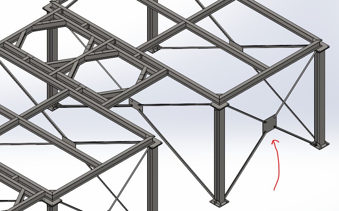
- St. Andrew's cross bracing throughout, with ties between the three platforms so the modules act compositely.
- Horizontal diaphragm bracing in the upper plane of each module, carrying lateral action in the roof plane and leaving the underside clear.
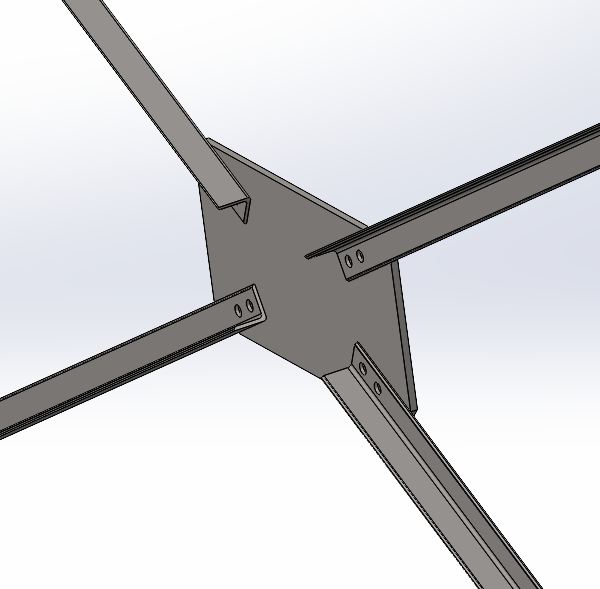
- Knee bracing on the front face, which had been entirely open.
- Brace sections resized, selected on the compression case — buckling slenderness and section classification — rather than on tensile capacity.
- Mitred corner nodes enlarged with the double-mitre detail, welded on the inner face, with radiused transitions moving the weld toe away from the reentrant corner.
- Transverse web stiffeners at the reactor support nodes, closing the open I-section locally into a rigid rectangular cell so the reaction is carried flange to flange rather than by local bending of the web.
- Gussets and haunches at the reactor supports to control the twisting observed in Rev 0.
Recorded for traceability: in an intermediate run the reactor forces had been entered as per-element rather than total values, tripling the load actually applied at the three support points and producing a spurious failure pattern. All results reported here use total forces distributed across the three supports, consistent with Rev 0.
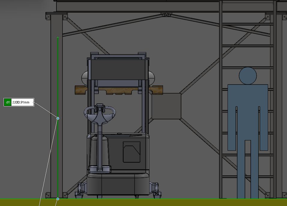
The knee brace is where the constraint becomes geometry
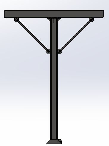
The knee braces sit at 2,200 mm clear height above floor level. That preserves the passage of pallet trucks and forklift traffic beneath the platforms — the client's requirement to use the underside for raw-material storage — at the cost of limiting the working height of the truck mast, which remains workable retracted.
This is the compromise that allows the front face to be braced at all. A full-height cross in that plane would have closed the access the client explicitly asked to keep.
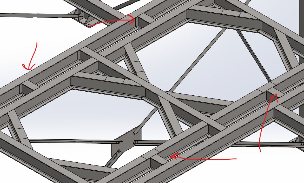
Gravity alone — satisfactory, and not the governing case
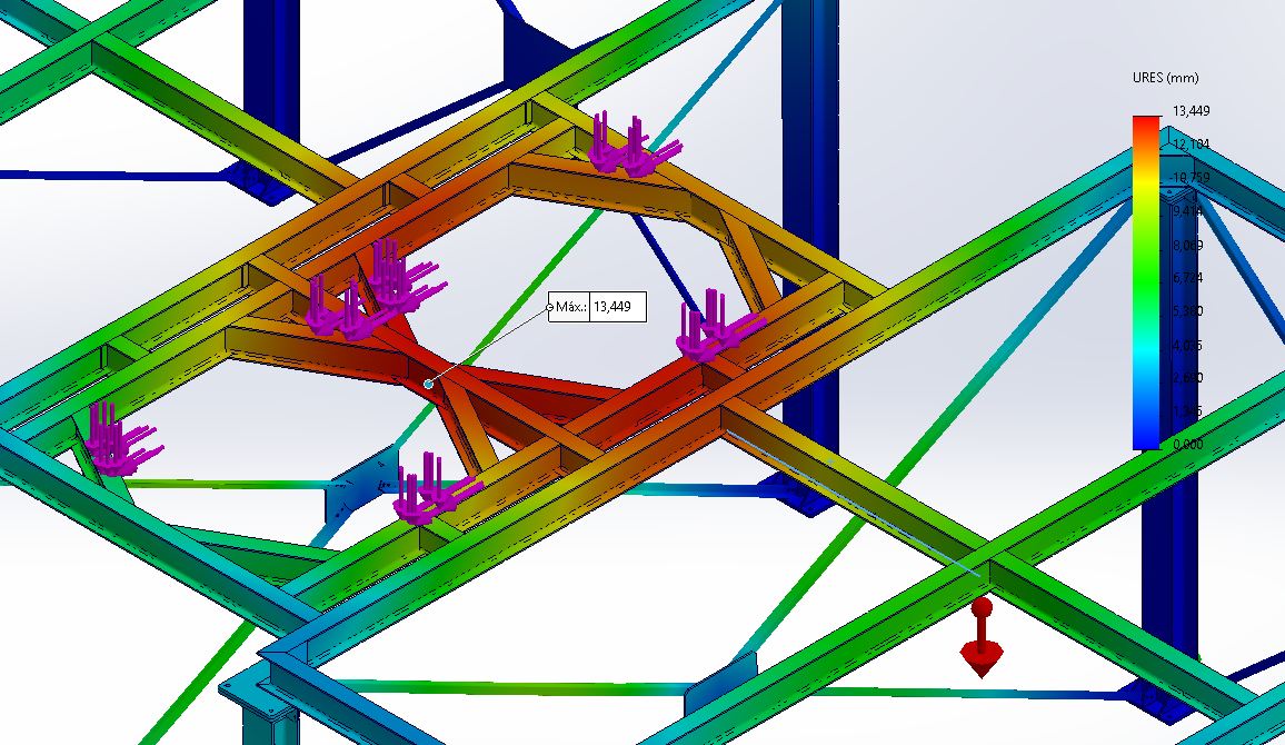
Under vertical loading the structure performs well throughout. The corrective measures have removed the concentrations that dominated Rev 0 and no member approaches yield. Maximum resultant displacement reaches 13 mm, accepted at this stage.
That 13 mm corresponds to the amplified load, not the service condition, and is reported as a screening value. Its relevance beyond serviceability is that deck flexibility governs the natural frequency of the reactor supports — and confirming that frequency stays clear of the agitator operating speed is exactly what remains held pending the motor data.
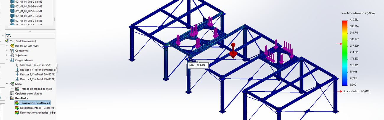
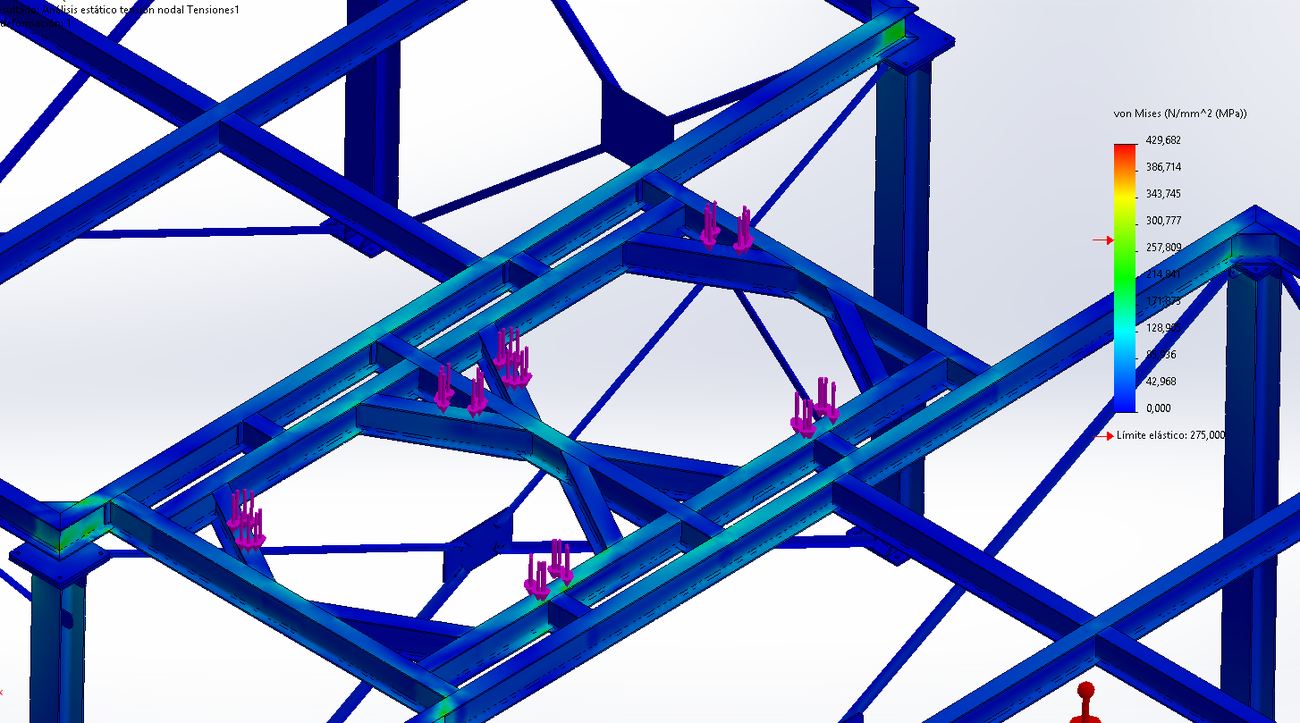
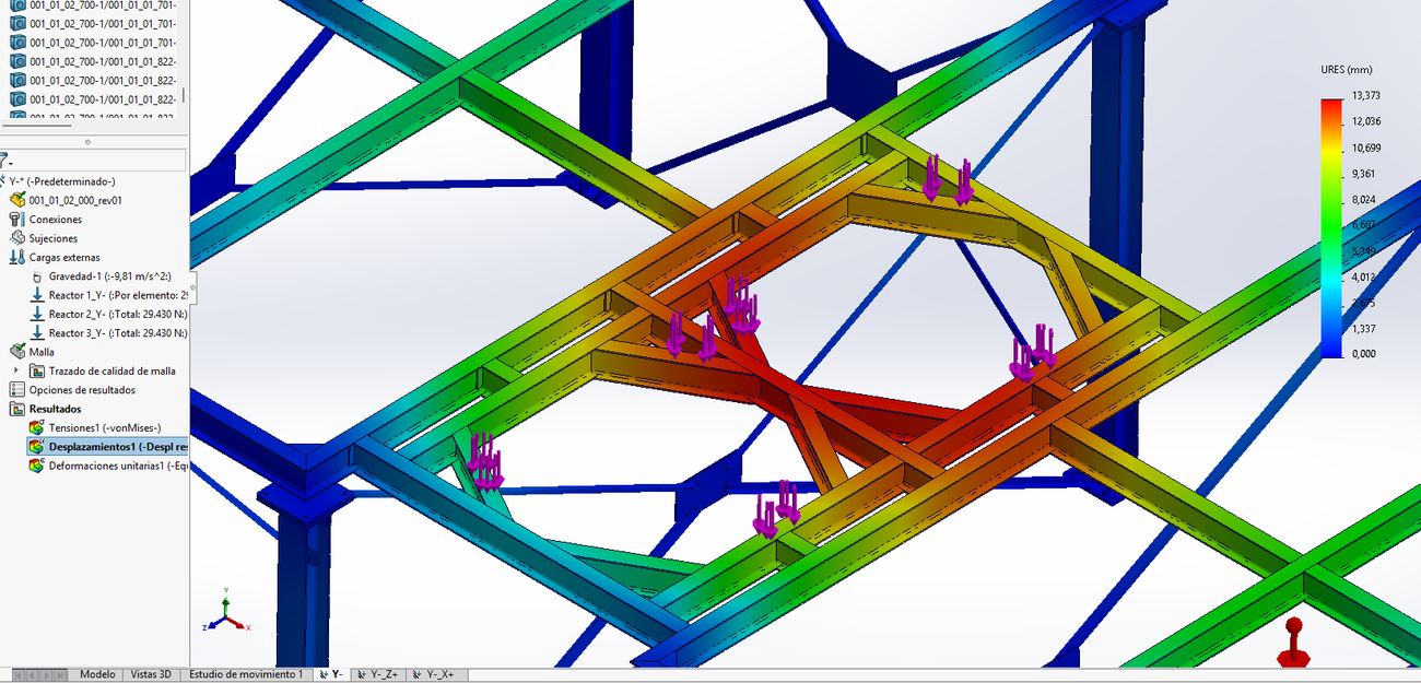
G+Z — acceptable, and a fix deliberately not applied
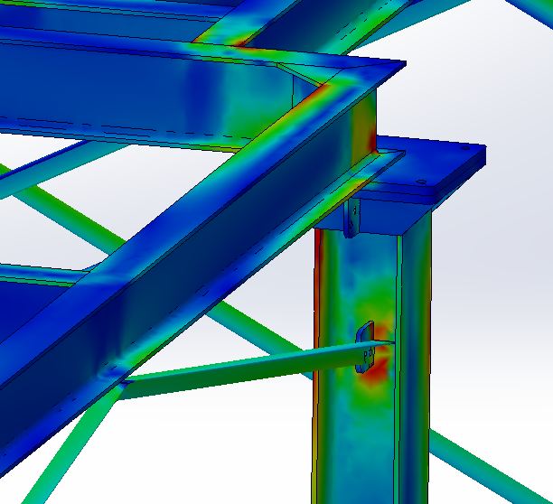
The +Z response is acceptable. Small zones of elevated stress remain, and their character is worth noting: they do not read as the numerical singularities identified in Rev 0 at the sharp reentrant corners, but as a genuine reaction to twisting of the members.
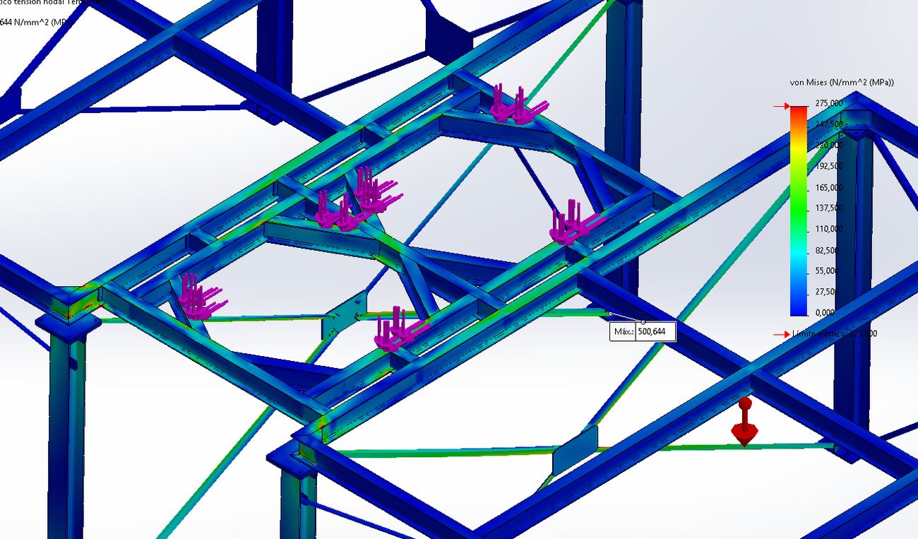
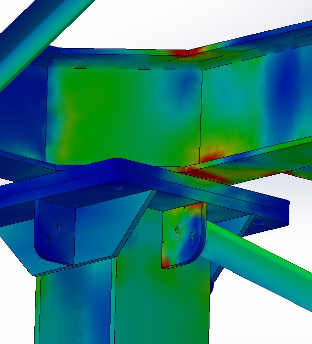
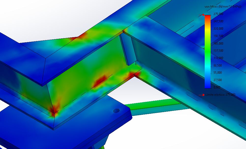
These could be resolved locally with additional stiffening. I deliberately did not do it. Local stiffening at each affected point adds fabrication complexity without addressing why the members are twisting in the first place, and the same demand is expected to fall away once the underlying cause is treated.
This is a design decision, not an omission. Where a symptom appears in several places at once, treating each occurrence individually is usually a sign that the mechanism producing them has not been identified yet. The measure is held, and reconsidered only if the concentrations survive the next revision. Whether they are genuine or artefacts is to be settled by local mesh refinement: a peak that keeps escalating as the mesh refines is an artefact of the modelled geometry; one that stabilises is a real demand.
G+X — still governing, and now the pattern says why
The twisting of the deck beams now reaches the flanges along their length rather than staying confined to the connections. That distribution is characteristic of weak-axis bending and torsion of the members themselves, and it offers two responses: stiffen the flanges at intervals, or reduce the torsional demand at source.
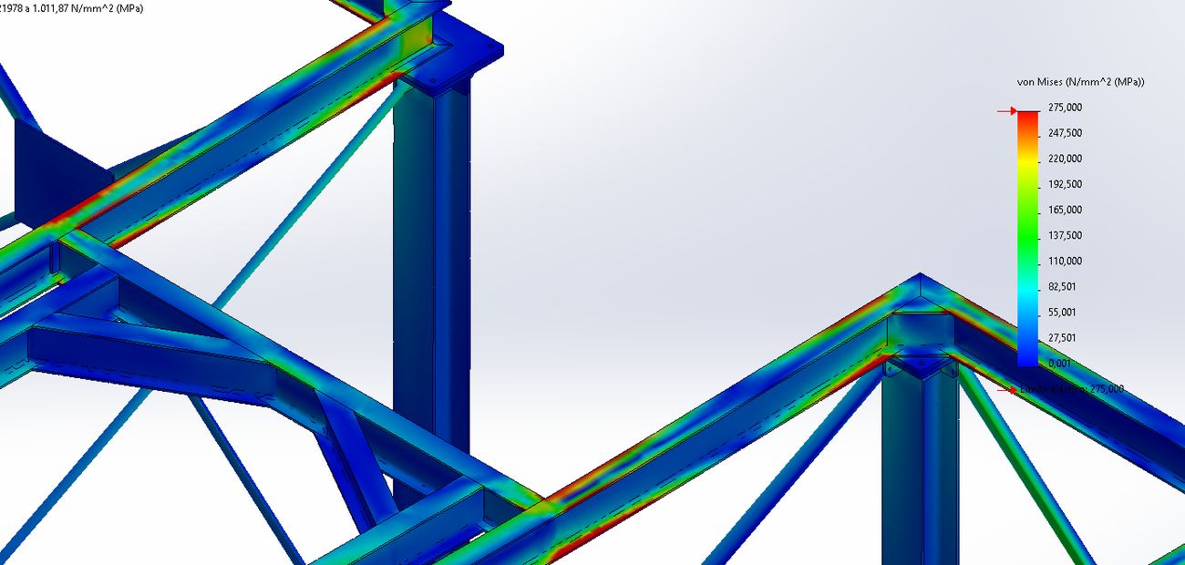
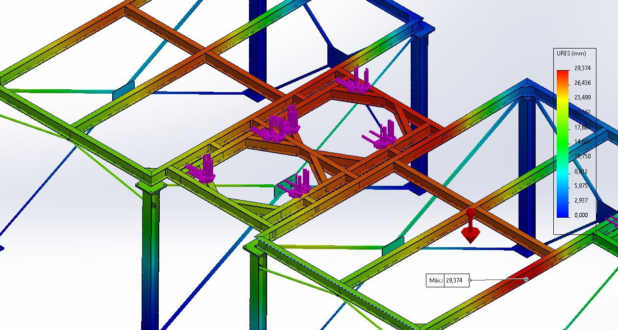
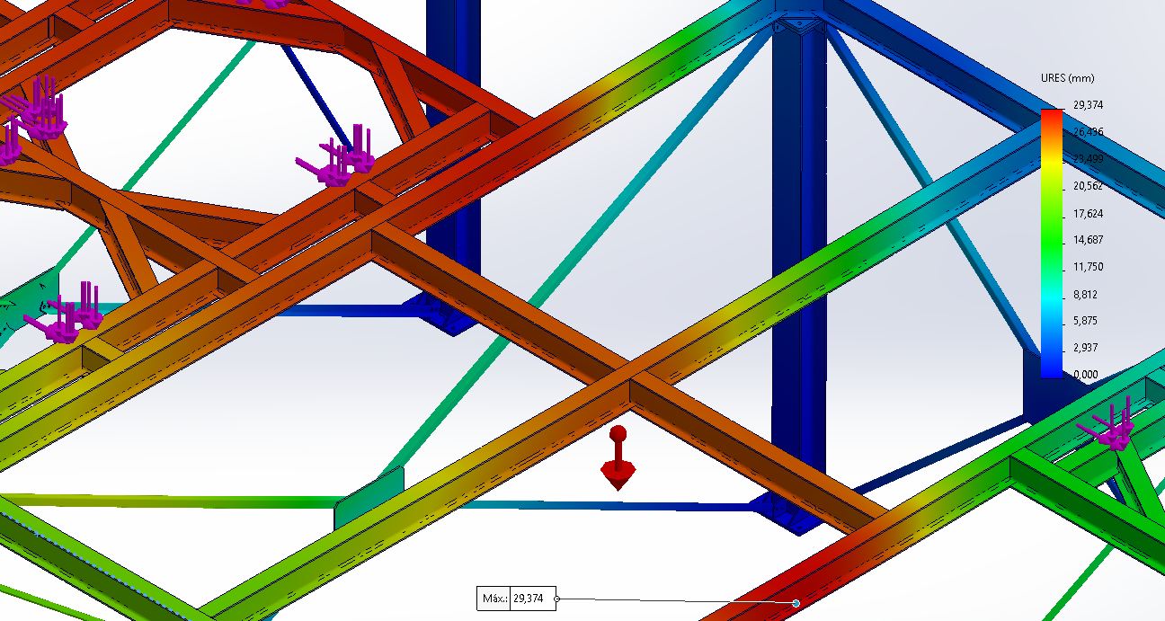
The displacement results quantify both the improvement and its limit. Maximum resultant displacement falls from 57 mm unbraced to 30 mm with the full package in place — roughly half. The measures are demonstrably effective. They are also insufficient: 30 mm remains well beyond the H/300 serviceability limit adopted for this type of service platform, and the residual displacement is again torsion of the deck rather than any local deficiency.
Why the X axis keeps governing
The pivot · end of Rev 1The Rev 1 measures were simple, appropriate and economical. They were correctly identified. Their effect is measurable. What they do not do is act on the variable that dominates the X direction.
Cross bracing, diaphragms, knee braces, stiffeners and larger brace sections all increase the stiffness of members and joints. None of them shortens the distance the deck must span to reach a point of support.
That distance is the constraint. The columns are widely spaced, so lateral action travels a long way through the deck before it reaches a braced plane. Deflection scales with the cube of the span, so past a certain point no realistic amount of additional stiffening compensates for the distance to the columns. The observed behaviour matches that reading: demand distributed along the flanges rather than concentrated at joints, and a global twisting of the deck rather than a local failure.
Stiffening the flanges at intervals treats the symptom — it adds material along members whose actual difficulty is that they are being asked to carry lateral load across an excessive span. Reducing that span treats the cause, and does it with one intervention instead of a distributed one. That is what Revision 2 does.
Revision 2 — discharge columns, and the final screening
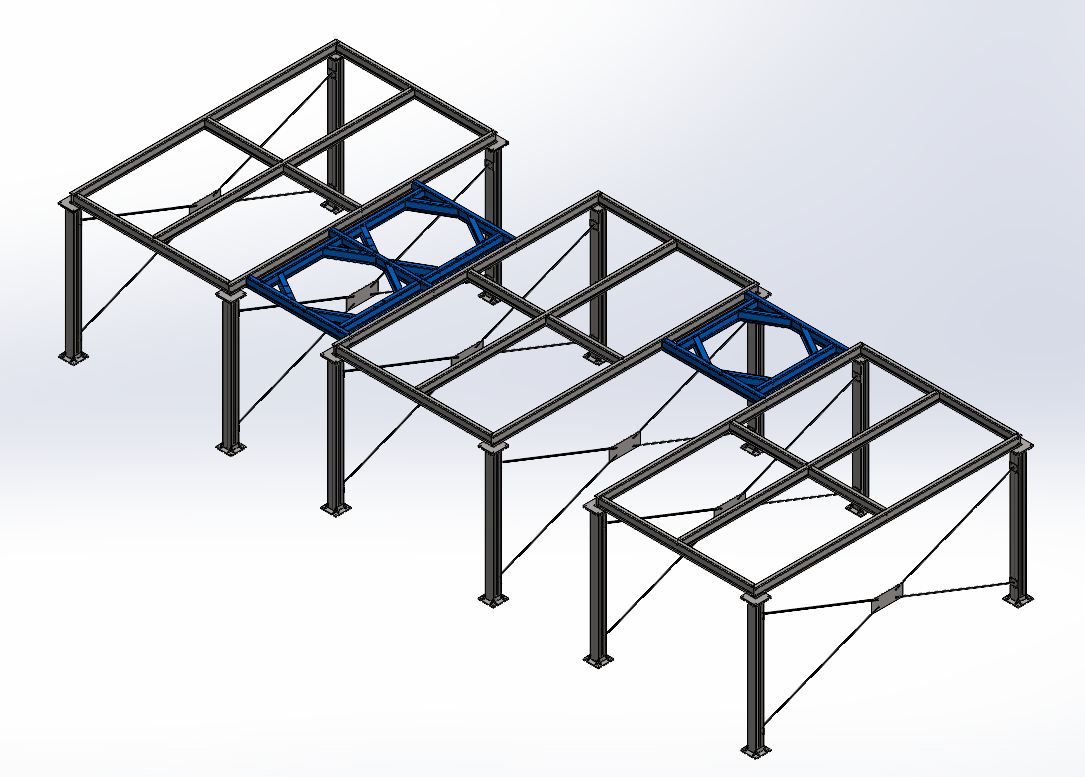
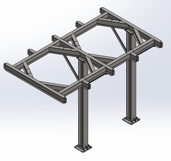
Rev 2 · finalRevision 1 proposed an intermediate support where the deck spans furthest. Revision 2 realises it as intermediate discharge columns beneath the reactors — members that shorten the governing span and serve the process discharge at the same time. Each is oriented with its strong axis aligned with X, stiffened to its head plate by triangular gussets, and bolted to a plate welded to the reactor support structure. Everything else from Revision 1 is retained.
The intent is twofold. The columns halve the span the deck must cross in the governing direction, which given the cubic relationship is the single most effective lever available. And they introduce support precisely where the displacements peaked and where the deck twisting originated, so the torsional demand falls away rather than having to be resisted member by member.
Gravity (−Y) — the columns remove the demand
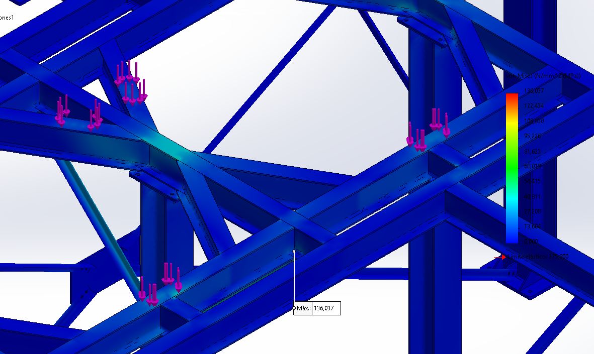
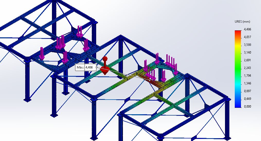
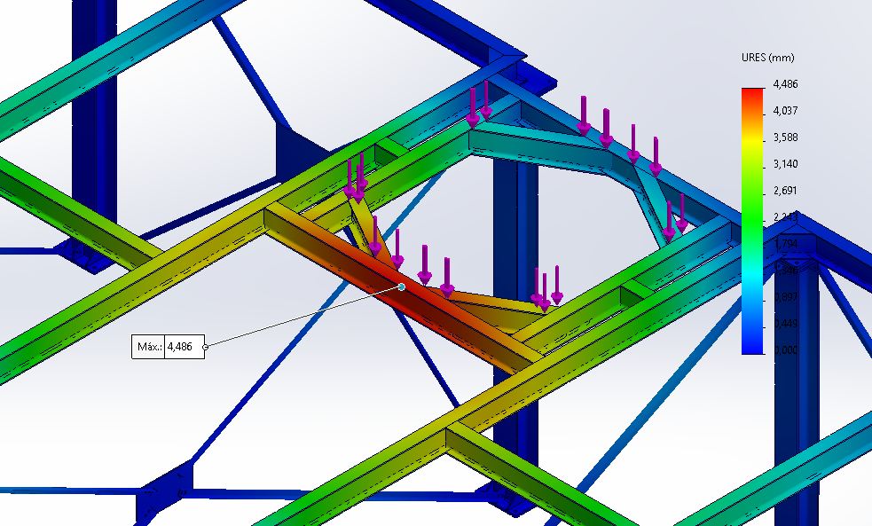
Under vertical load the discharge columns effectively remove the displacements and the mechanical demand the structure previously had to carry. Stresses are low throughout, of the order of 136 MPa against a 275 MPa yield. The residual displacement concentrates on the single rear reactor frame — the one without a discharge column — and reaches 4.5 mm, accepted at this stage.
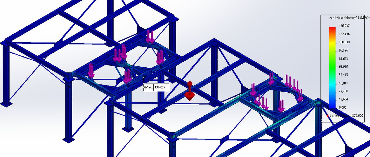
Gravity + lateral (+Z) — the braces do their job
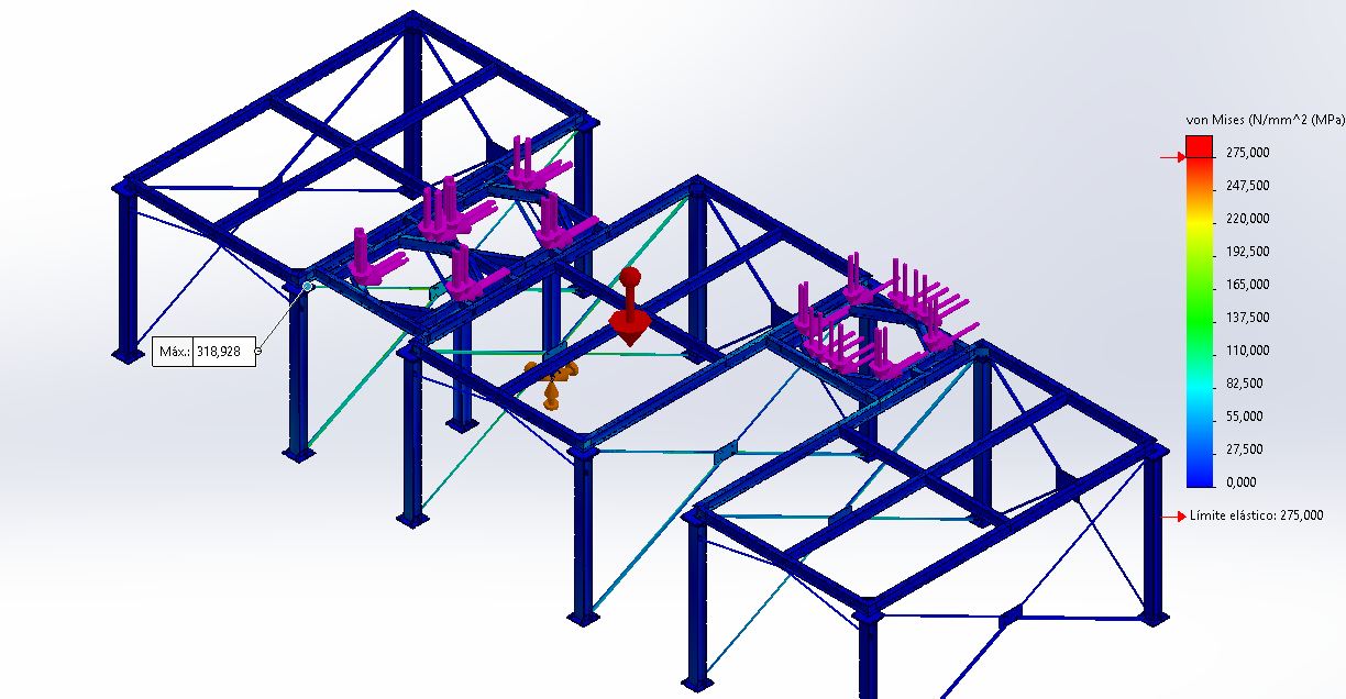
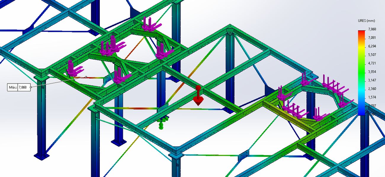
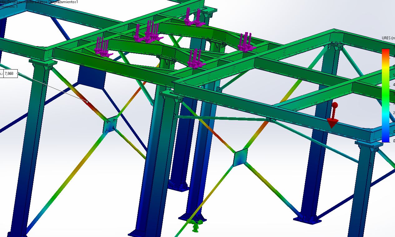
In +Z the load path into the braces behaves correctly. The angle braces on the first platform are more heavily worked than those on the second, but the platform itself takes almost no displacement in Z: the bracing is carrying the lateral action as intended, which is precisely its purpose. In stress the structure is comfortably overdesigned in this direction.
That the diagonals are visibly loaded is itself the confirmation the Rev 1 pivot was waiting on — the load path to the braced planes is complete, so the residual X movement is a span-and-stiffness problem the columns are the right answer to, not a broken load path.
Gravity + lateral (+X) — still governing, now resolved
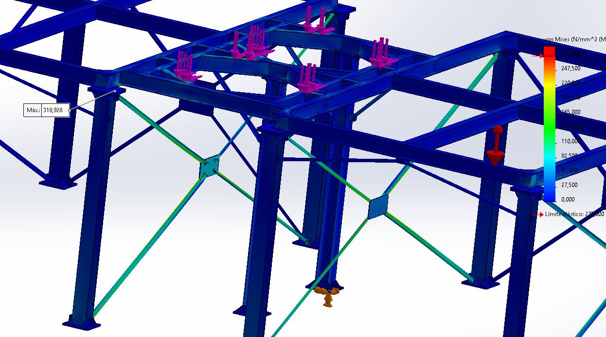
The +X direction remains the governing case. In stress the structure is not in difficulty; the demand concentrates at the bases of the discharge columns directly beneath the reactors, and at the head gussets. These are connection-region concentrations, not member failures, and their treatment belongs to the connection-design phase below.
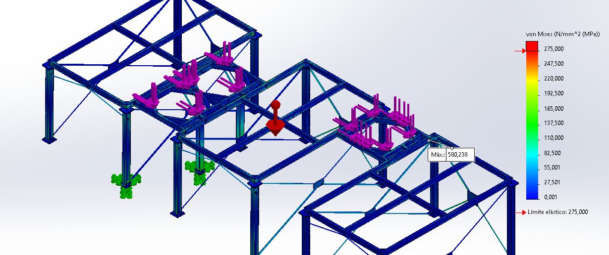
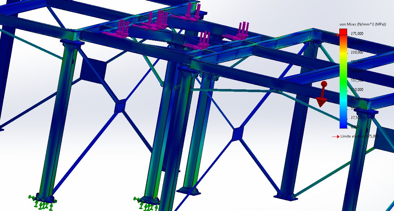
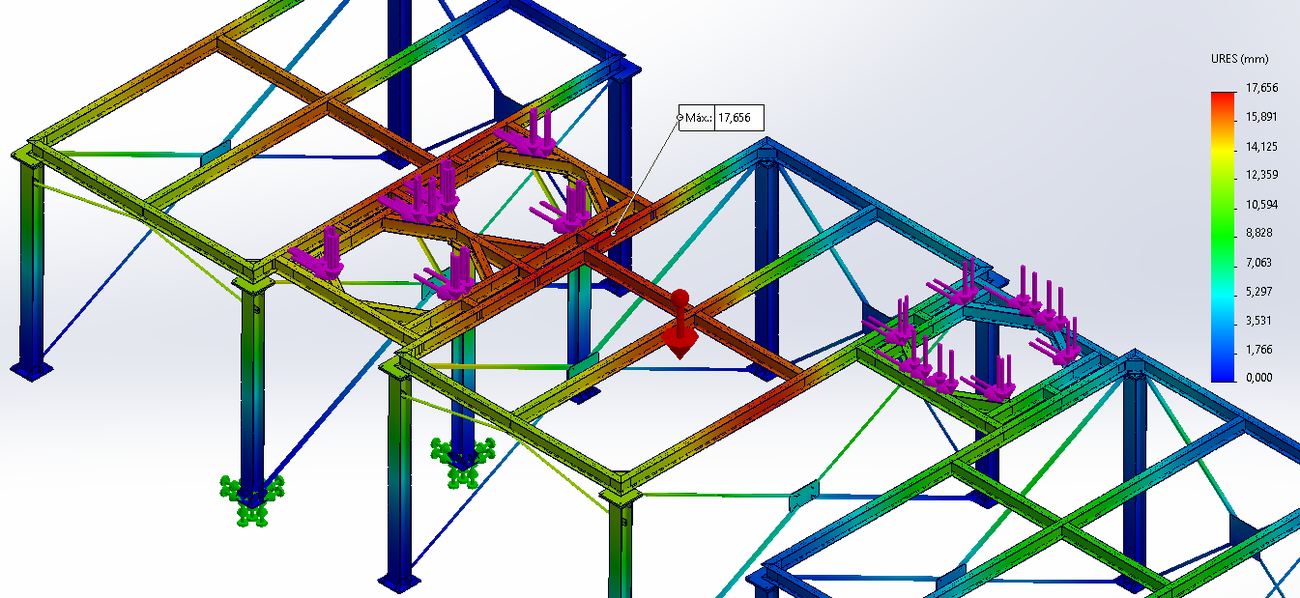
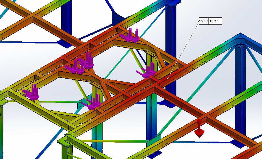
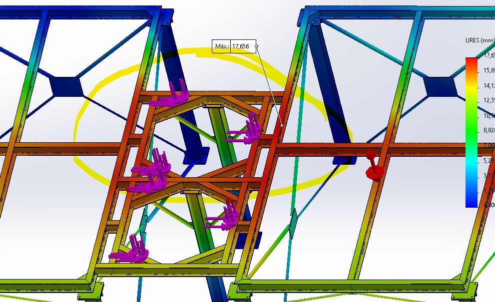
The maximum resultant displacement is 17 mm. Across the three revisions the X-direction movement has come down from 57 mm, through 30 mm with bracing alone, to 17 mm with the discharge columns in place. The columns resolved the vertical and axial demand entirely and roughly halved the residual lateral movement.
The last millimetre — and the limit I chose to keep
Rev 2 · section 7The element that controls X is the deck beam that spans 5,082 mm and deflects perpendicular to its axis under the lateral action. The serviceability criterion adopted is L/300, applied to that span, giving a limit of 16.9 mm. The computed displacement is 17 mm.
So the structure fails L/300 by a tenth of a millimetre, and I state that plainly. I kept L/300 deliberately, as the stricter of the two common serviceability limits. L/250 would give 20.3 mm and would classify the result as compliant with room to spare — but the more rigorous limit is the one I held myself to, and the marginal exceedance is declared rather than argued away by relaxing the criterion.
Choosing the looser limit to turn a fail into a pass is the easiest move in the report and the least honest. The value of a serviceability check is only as good as the limit you refuse to move.
Why the exceedance is accepted, not chased
The basis is the conservatism already built into the load case. The reactor is loaded at its theoretical maximum design charge amplified by 1.5, and the whole of that amplified load is then applied laterally. Neither condition reflects operation. In service the reactor works at roughly three quarters of its nominal charge rather than the theoretical maximum, and the agitation is slow and gentle, so only a fraction of the mass acts laterally rather than its full amplified value.
A 17 mm displacement under this severe idealisation corresponds to a substantially smaller movement in service. The result is accepted as sufficient — not optimal — in keeping with the client's priority of economy: closing a fractional exceedance under a deliberately punishing load would require additional columns and bracing that the real operating condition does not justify.
Base connections — reading the reactions correctly
Rev 2 · section 8The discharge columns act as cantilever masts resisting the lateral action, and their bases carry the resulting overturning. The support reactions were extracted from the model to set the design actions for the connection phase: at the column bases, an axial force in the shaft of the order of 45 kN, and at the plate-to-slab interface a horizontal shear of 24–25 kN together with a net vertical compression of the order of 37 kN and its associated base moment.
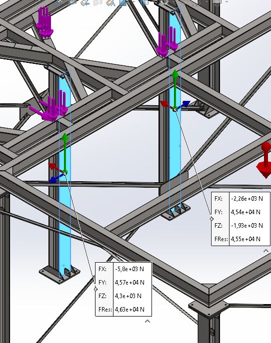
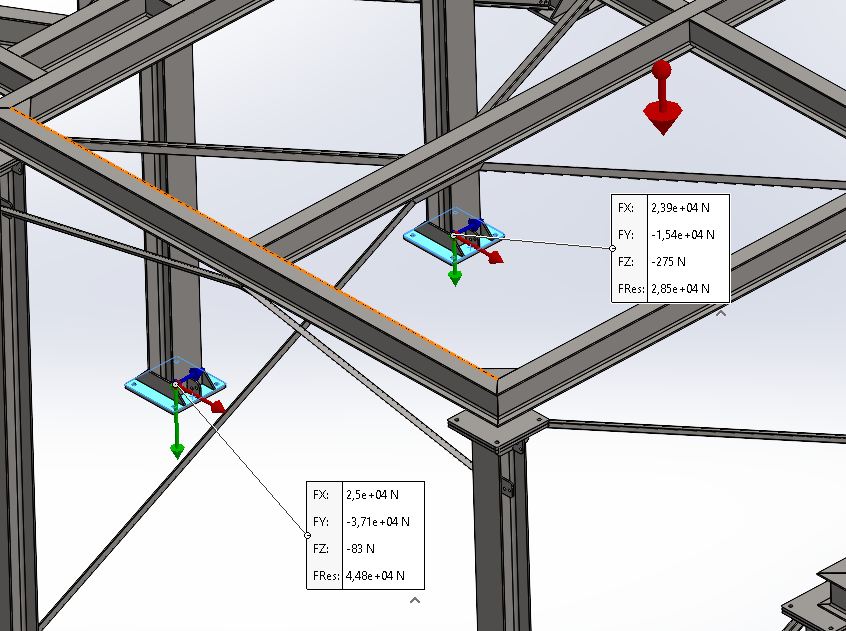
The detail worth pausing on is the bolt tension. It is not the net vertical reaction of the plate. Under the base moment, even where the plate reaction is net compressive, the windward anchors are in tension while the concrete on the opposite side takes the compression. The anchor tension is set by the internal couple — base moment over lever arm — resolved in the connection-design phase, and this uplift is expected to govern the base detail. Reading the net reaction and sizing the anchors to it would quietly under-design the connection.
The bases are designed as moment-resisting (fixed): a 20 mm base plate of 400 × 400 mm with eight M16 anchors. The plate thickness provides the rotational stiffness; enlarging the plate to 400 × 400 lengthens the anchor lever arm while the eight anchors provide the tensile resistance for the uplift. This is a connection-design decision and needs no further simulation run — it is adopted directly into the definitive design.
A precaution specific to this installation: the fixing is by chemical anchor and threaded rod, in an ATEX-classified zone where the process product attacks carbon steel, under cyclic load. The resin should be a grade rated for aggressive conditions and the threaded rod protected or stainless, consistent with the corrosion strategy adopted for the rest of the structure. Verification of the anchorage to the concrete — pull-out, concrete cone, edge distance — and of the slab and ground is explicitly outside this study's scope, since no data on the existing slab or soil is available; the design actions above are delivered as the input for that verification.
Where it lands, and what remains
Rev 2 · section 9The configuration is resolved and judged admissible for the client's requirements. Under vertical and +Z loading the structure is comfortable in both stress and displacement. In the governing +X direction the displacement is 17 mm against an L/300 limit of 16.9 mm on the 5,082 mm deck beam — a marginal exceedance, declared and accepted on the basis of the severe conservatism of the load idealisation, in keeping with the client's priority of economy. The solution is presented as sufficient rather than optimal: a robust, low-cost compromise that works within the open-underside constraint the client imposed.
Carried into detailed design
- Connection design to EN 1993-1-8, with the anchor pull-out at the discharge-column bases as the governing check, alongside the bolted and welded connections of the platforms and braces. The base plates are fixed at 400 × 400 × 20 mm with eight M16 anchors and need no further simulation.
- Anchorage to the slab, and assessment of the slab and ground — outside the present scope, to be confirmed against the real properties of the support using the design actions delivered here.
- Eigenvalue buckling and the second-order assessment, now meaningful on a configuration that passes the linear screening.
- Modal verification, held pending the motor data, to confirm the natural frequency of the supports stays clear of the agitator operating speed.